Standard LEDs
Diotec Semiconductor Standard LEDs are widely used for various lighting needs such as optical indicators, signal lights, marking lights, display backlights, interior and furniture lighting and much more.
New approaches even use standard LED arrays to replace fluorescent lights (Neon Tubes). Standard LEDs are robust, long-living, and available in high volumes at a low cost. Standard LEDs power consumption is on an extremely low level below 100 mW. The driving current of these devices is typically 20mA, resulting in a forward voltage drop between 2 and 4V. The following describes a cost effective solution to drive such LEDs by means of current limiting diodes CLxxMyy series offered by Diotec. They are available with 15, 20, or 40mA and maximum 90V: CL15M35, CL20M35, and CL40M35 in SMA package, and CL15M45, CL20M45, CL40M45 in SMB.
Current Limiting Diodes (CLD)
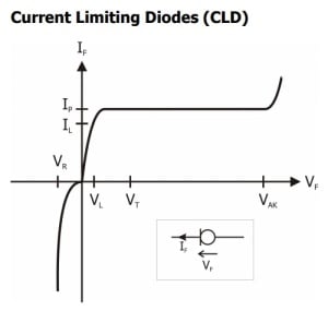 Like a Zener diode keeps a voltage constant over a wide range of Zener current, the Current Limiting Diode or CLD keeps a current constant over a wide range of forward voltage. The left figure shows the typical IF, VS. VF curve of such CLD device, including the symbol and current/voltage definitions. When applying a positive voltage from anode to cathode (indicated by cathode mark), the current rises until it reaches a constant value Ip. The start of this current limiting area is defined by the limiting voltage VL, above which IL = 80% of Ip is reached. Ip remains constant, unless a maximum admissible voltage VAK is reached, above which a breakdown happens and the device can be destroyed. In reverse direction, the voltage VR is quite quickly reached. So operating voltage range is between Vl and VAK, where the current is kept to a constant value Ip; the reverse direction is not typically used.
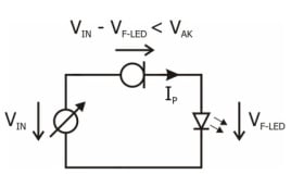
Taking the function of the CLD into account, such device can be used to drive LEDs with a constant current Ip from a variable voltage source VIN, see figure to the right. The only condition is to limit the voltage across the CLD to a value less than VAK; that voltage is the difference between VIN and the voltage drop at the LED, VF-LED.
 The CL20Mxx is designed for an Ip of 10mA, which is the typical current for Standard LEDs; the VAk is 90V. So in the easiest case, this CLD can be used to drive a single LED from a voltage source ranging from about 10V DC up to 90V DC. For higher driving currents, the CL40Mxx offers Ip of 40mA. CLDs can also operate in parallel; of course then the power dissipation / power losses will increase as well.
In most cases there is an AC voltage source, so additionally a (bridge) rectifier device is required. If the circuit is connected directly to the 110V/230V AC mains, VIN can reach quite high levels up to 350V peak. So existing designs require a lot of additional devices, in order to reduce the incoming voltage to an acceptable level; they further require electrolytic capacitors to keep that voltage constant. As a result, such circuits are complex and expensive, and their lifetime is limited mainly by the electrolytic capacitors used.
The following describes how by means of just a bridge rectifier, one or two CLDs, either an array of LEDs or an AC capacitor, a circuit for direct operation at 110VAC or 230VAC mains can be built.
Solution up until now: Requiring 5 components and having limited lifetime.
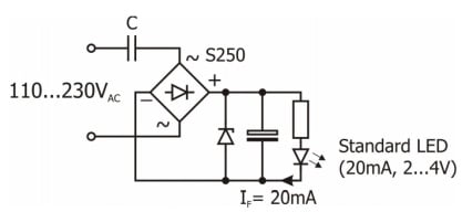 The right picture shows how up until to now LEDs are driven at AC mains. The Zener diode, electrolytic capacitor and power resistor is required to keep the forward current IF through the LED constant. The electrolytic capacitor has the shortest life-time of components in the circuit and is the limiting element. During turn-on, a current peak can occur at the bridge, caused during initial charge of the AC and electrolytic capacitor. Therefore here the S250 by Diotec is used, featuring a very high forward surge rating of 40A (at 50Hz).
New Solution, Example 1: Only 3 components and improved lifetime
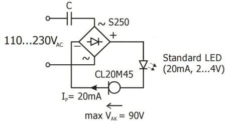 The circuit on the left simply needs 3 components to drive one (or more) Standard LEDs at
a wide input range. The AC capacitor C has a certain dynamic impedance Xc = 1/ (2πfC). Depending on the output power (and related to that, the input or mains current), there is a voltage drop across this impedance. C has to be chosen such way that the voltage drop is big enough to ensure that V AK of the CLD is not exceeded.
New Solution, Example 2: Only 3 components for driving LED arrays at 110V AC
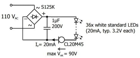 Here not only one, but an array of Standard LEDs is used. The resulting voltage drop across the series of LEDs is big enough to ensure V AK is not exceeded. Thus, by only one rectifier bridge and one single CLD a complete LED luminaire, operated at 100V AC, can be done. The here used Protectifiers birdgem S125k has advantage of an increased ESD capability, and provides as such additional protection for the LED array.
New Solution, Example 3: Only 3 components for driving LED arrays at 230V AC
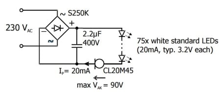 Here the same circuit, but operated at 230V AC mains. Due to the higher peak voltage, more LEDs have to be connected in series. Anyway, a single rectifier bridge is enough to complete the whole circuit! The here used Protectifiers bridge S250K has the advantage of an increased ESD capability, and provides as such additional protection for the LED array.
* An additional mains fuse is recommended to provide circuit protection in case of any unforeseen shorts.
Why We Are One
For over 40 years, IBS Electronics Group has provided a broad range of integrated supply chain and electronicsmanufacturing solutions tailored specific to our customer's operations. As your one source for the industry’s top brands all in one place, our engineers specialize in reducing supply chain complexity and are here to provide you with dedicated support from prototype to production.


.png?resizemode=force&maxsidesize=96)